
Overview
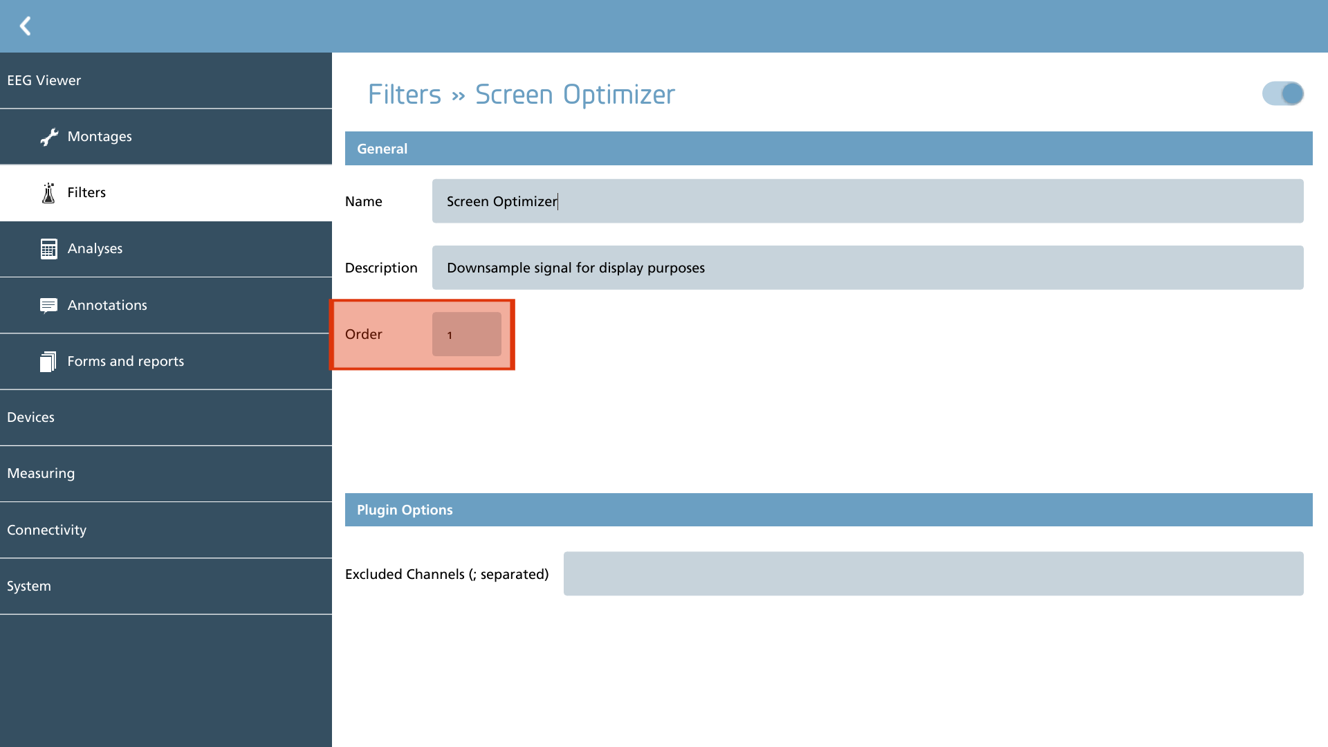
Filter elements are structured according to specific plugins and are processed in a designated order, resembling a pipeline concept where signals traverse through various filters. This processing sequence is indicated in each filter element by the input field labeled ‘order’. Filters are executed from the lowest to the highest order numbers.
It is important to note that the order specified here does not pertain to the characteristics of the filters themselves. Modifying this setting solely influences the sequence in which the filters are applied to the signal.
Plugins
The plugins serve to define the available filters. Some plugins necessitate additional configuration, while those that do not require specific configuration are not discussed in detail here. Below is the current set of plugins along with a brief description of each:
|
Icon |
Description |
Configurable |
|---|---|---|

|
Average Provides moving average subtraction filter |
Yes |

|
Butterworth Provides basic IIR filtering (HP, LP, BP, BS, Notch) |
Yes |
|
Decimation Provides a decimation filter for screen optimization |
Yes |
|
FIR Provides basic FIR filtering (HP, LP, BP, BS, Notch) |
Yes |
Average
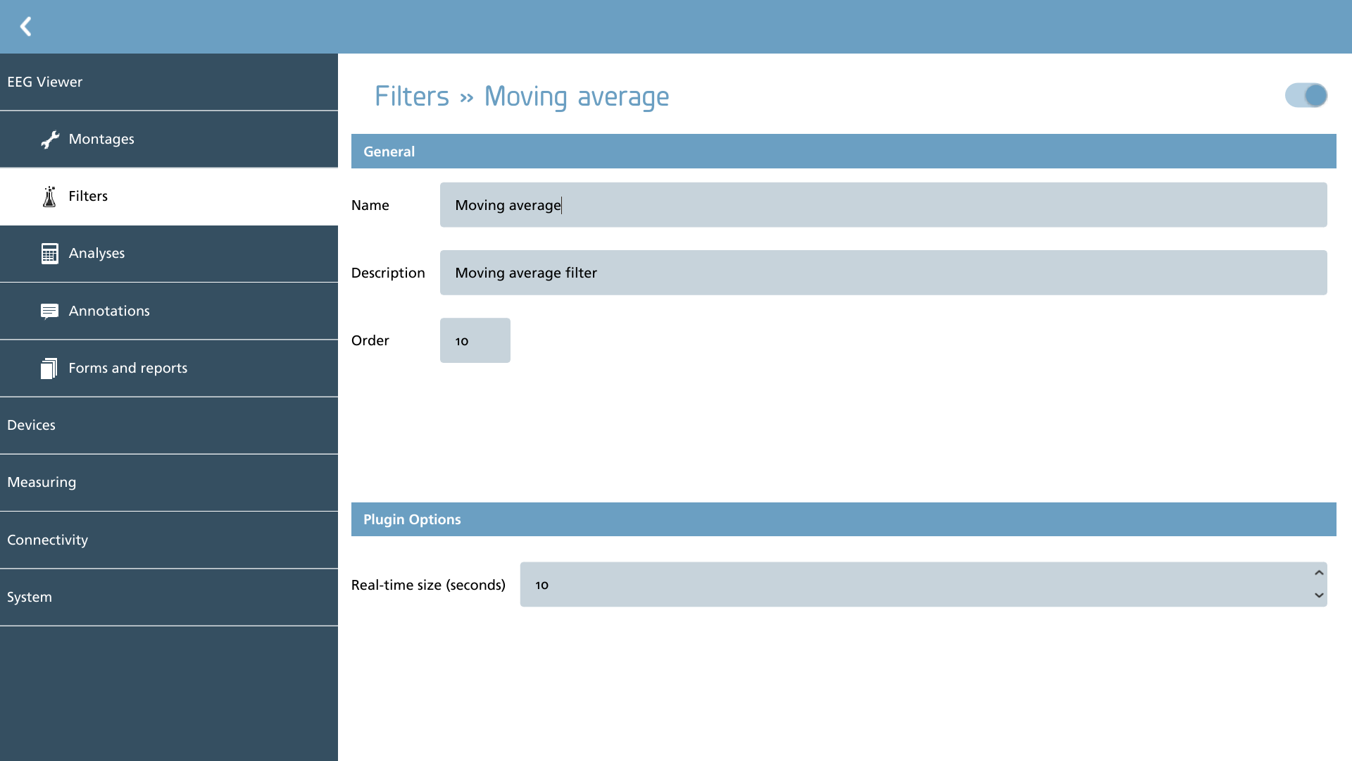
The moving average filter operates by calculating the mean amplitude of a signal over a designated time period, referred to as the ‘real-time size’. This method provides a rapid computation that is particularly advantageous for addressing significant offsets in signals captured with DC coupled amplifiers, thereby eliminating the necessity for more complex high-pass filters. The default setting for this filter is 10 seconds, although this can be modified as needed. It is advisable to configure this value in accordance with the viewing interval that is typically utilized.
Butterworth
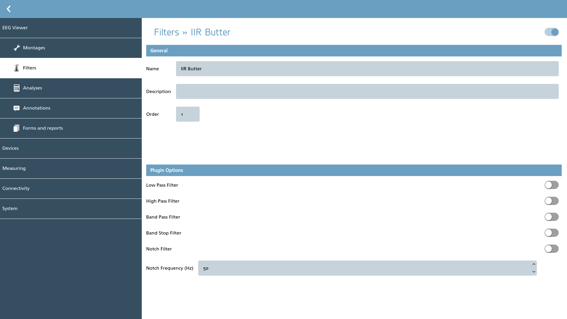
The IIR-based Butterworth filters facilitate various types of signal processing, including low pass, high pass, band pass, band stop, and notch filtering. Within the configuration settings, users have the ability to enable or disable these filters. Enabling a filter makes it accessible for use in the viewer, necessitating further setup. Conversely, disabling a filter renders it unavailable for use in the viewer.
It is important to note that the notch frequency should align with the frequency of the mains supply, typically either 50 or 60 Hz.
The Butterworth filters utilize a standardized third-order filtering technique, which is designed to provide a smooth frequency response. This approach is essential in signal processing, as it ensures minimal distortion of the signal within the passband.
Decimation
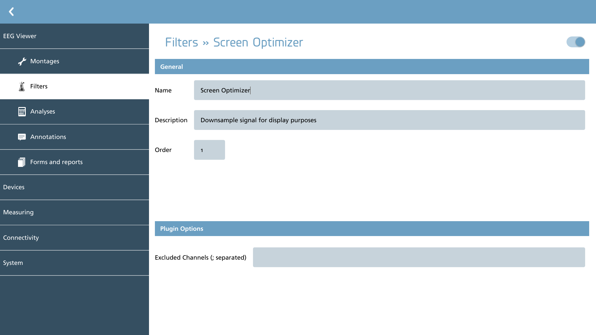
The decimation filter functions by down sampling each signal in accordance with the actual screen resolution. This filter is commonly employed as an initial filter (order = 1) to enhance the efficiency of filtering in subsequent stages. Given that the impact of down sampling can be quite pronounced at high sample frequencies, it may be advantageous to exclude specific channels, such as trigger channels. This exclusion can be accomplished by specifying the channels to be omitted from filtering in a semicolon-separated format (e.g., ‘trig1;trig2’).
It is advisable to avoid disabling this filter when conducting recordings or reviews at high sample frequencies, as the computational demands of subsequent filters may become excessively high, potentially hindering the ability to perform real-time filtering effectively.
FIR
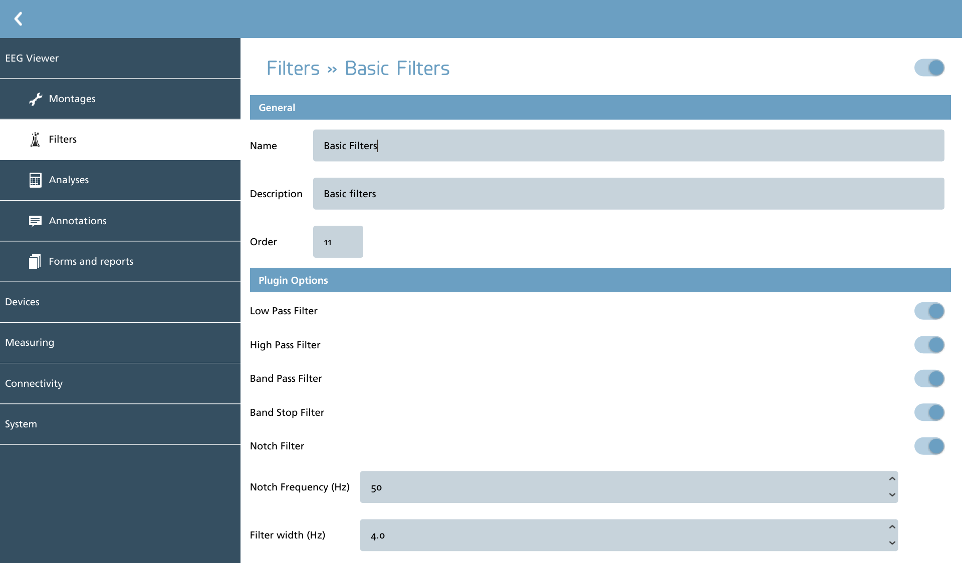
The FIR-based filters facilitate various types of signal processing, including low pass, high pass, band pass, band stop, and notch filtering. Within the configuration settings, users have the ability to enable or disable these filters. Enabling a filter makes it accessible for use in the viewer, necessitating further setup. Conversely, disabling a filter renders it unavailable for use in the viewer.
It is important to note that the notch frequency should align with the frequency of the mains supply, typically either 50 or 60 Hz. FIR-based filters do not exhibit an abrupt cutoff at the designated frequencies; instead, they feature a transition width, allowing for a gradual reduction in signal strength down to -60 dB. This transition width can be modified using the ‘Filter width’ setting, which is specified in Hertz (Hz) and determines the transition width across all filters. Commonly, values ranging from 3 to 5 Hz are utilized, striking a balance between accuracy and processing speed.
It is essential to recognize that setting a very small transition width can lead to increased calculation time and may introduce undesirable artifacts at the edges of the input frequencies.
Filtering, like all signal processing operations, modifies the original signal in ways that could potentially result in misinterpretation under certain circumstances. If uncertainty arises, it is advisable to revert to default settings or completely disable filtering.