
Overview
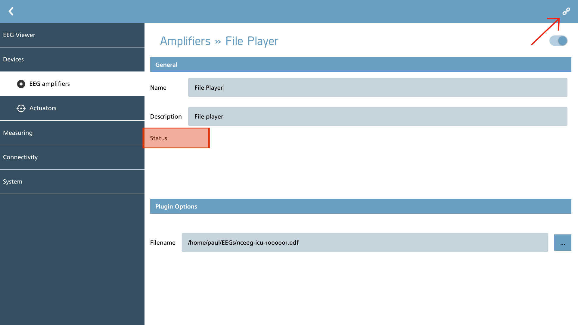
Upon successful configuration of the EEG amplifier, the activation of the connect button, situated in the upper right-hand corner, is permissible. Subsequent to the successful initialization of the device, a transition of the button's visual representation to a map icon will be observed.
|
Icon |
Description |
|---|---|

|
Connect Connect to the amplifier with the current settings. |

|
Edit channel map Display the channel map to edit the channel properties. |
During the initialization process, the corresponding status indicator serves to signify the initialization of the device.
|
Icon |
Description |
|---|---|

|
Initialization started Connection is being initialized to the amplifier. |

|
Initialization busy The amplifier is active and communication is in progress. |

|
Initialization passed The amplifier was successfully setup. |

|
Initialization failed There was an error accessing the amplifier. Check your settings and connections. |
Channel map
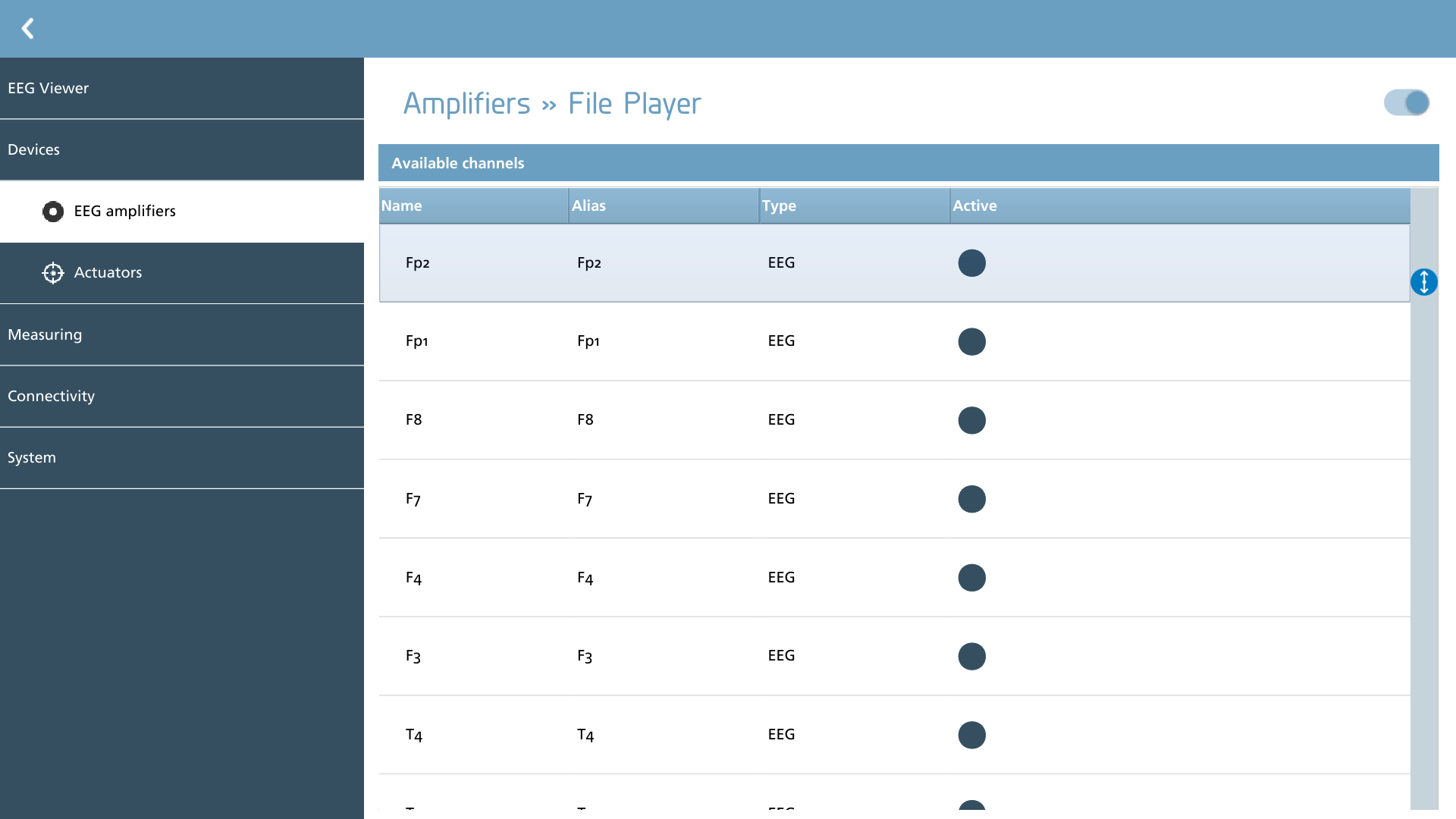
To set up the channels, one must click on the map icon, which will display a channel map. The amplifier may provide real electrode position names, numbers, or other technical designations, which will be displayed in the ‘Name’ column. It is essential to consult your specific amplifier’s user manual to ascertain the correct electrode positions corresponding to the returned amplifier channel names.
In instances where channel names differ from EEG electrode positions as defined by the 10-20 or 10-10 system, an alias must be employed. This alias effectively 'renames' the channel for subsequent internal use. The alias serves as the actual label utilized in montages and storage. To modify the alias, simply double-click on the current alias name.
When utilizing auxiliary channels for monitoring, such as ECG or EMG activity, it is considered best practice to rename these channels with an alias that reflects a more descriptive name (e.g., ECG instead of AUX1). This methodology offers several advantages:
-
Consistent naming of channels across files, irrespective of the amplifier used for recording;
-
Elimination of the need to modify montages each time;
-
Ensured consistency in analyses that expect these channels across different files.
It is important to utilize only alphanumeric characters in your channel alias. Symbols may not be interpreted correctly by other viewing software, potentially compromising the compatibility of your files. Special attention should be given to the use of the minus ('-') sign, as it signifies a reference.
The ‘type’ column indicates the channel type as reported by the amplifier. Channels are categorized by type and can be adjusted collectively within recording protocols.
To disable channels that are not intended for recording, simply toggle the active button.
Plugins
The plugins delineate the available amplifiers. Some plugins necessitate additional configuration, while those that do not require specific configuration are not discussed further here. Below is the current set of plugins along with a brief description of each:
|
Icon |
Description |
Configurable |
|---|---|---|

|
APEX Support for Artinis APEX amplifier |
No |
|
BrainTronics Support for BrainTronics EEG-1042 amplifier |
Yes |
|
Diagnostics Waveform generator for adjusting viewer settings |
No |

|
EEGO Support for ANT Neuro EEGO series of amplifiers |
No |

|
Fileplayer Plays back a recorded signalfile for testing / demo purposes |
Yes |

|
SAGA Support for Artinis SAGA32/64 series of amplifiers |
No |

|
Spiegelberg Support for Spiegelberg ICP monitors |
Yes |

|
TMSi Support for legacy TMSi amplifiers (Refa, Porti, Mobi) |
Yes |
While it is advisable to create multiple elements when utilizing various channel map configurations, it is essential to ensure that only one physical amplifier of each type is connected at any given time. NeuroCenter® EEG does not support simultaneous recordings from multiple amplifiers of the same type.
BrainTronics
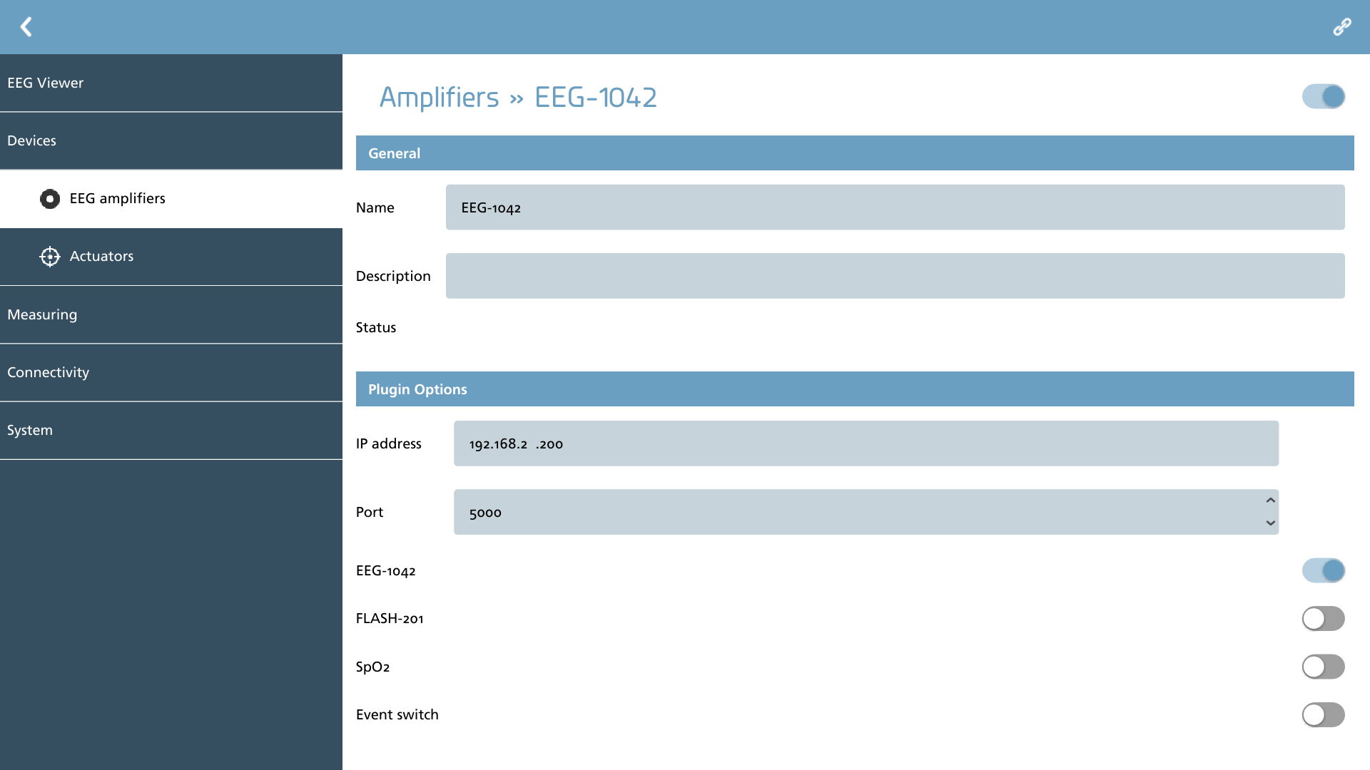
BrainTronics amplifiers utilize an ethernet-to-amplifier interface (ETHERNET-102) for connectivity. Consequently, it is essential to configure the IP address and the port number. Should there be any uncertainty regarding the port number, it is advisable to consult the BrainTronics user manual or to attempt using the default port 5000.
Additionally, the plugin requires prior knowledge of the devices currently connected to the BrainNet section of the interface. Therefore, it is important to adjust the corresponding switches to activate these devices and properly configure them within the channel map.
Fileplayer
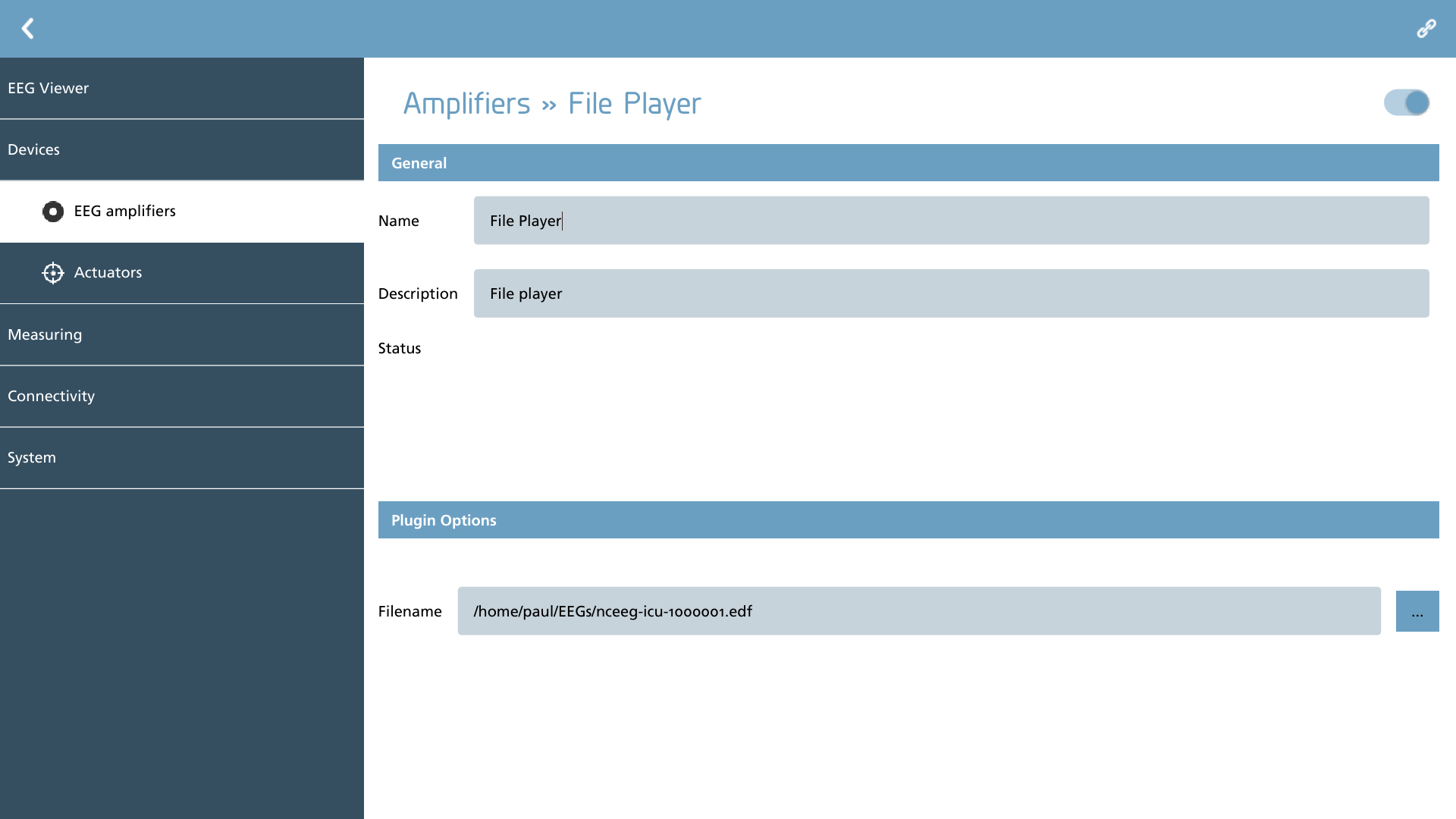
The fileplayer plugin serves the purpose of replaying a previously recorded signal file. To utilize this feature, one must select a filename by employing the browse button located adjacent to the filename field.
Spiegelberg
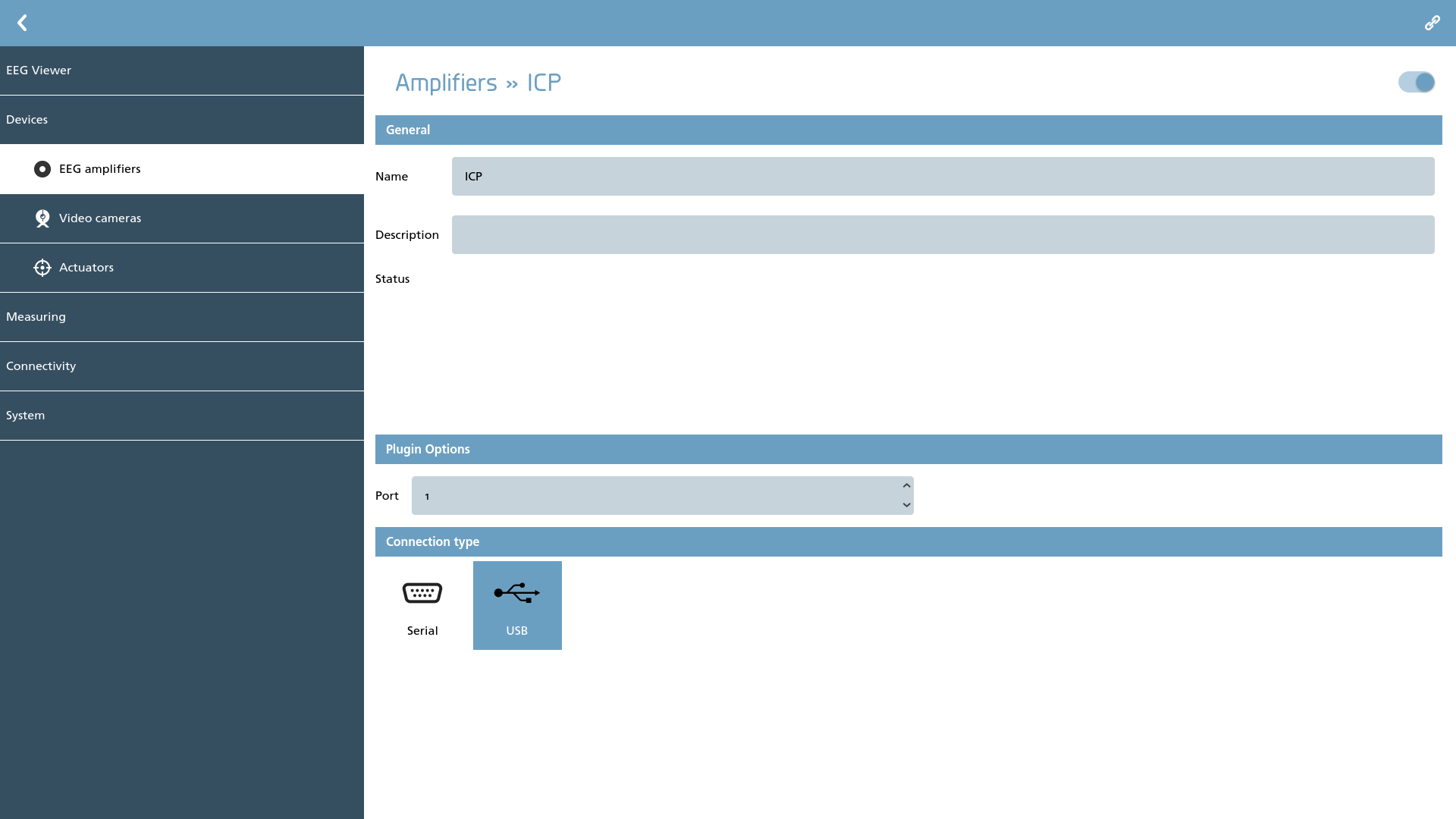
The Spiegelberg plugin is designed to facilitate the integration of ICP monitors from Spiegelberg. It is important to note that this plugin operates exclusively in conjunction with an EEG amplifier and is not intended for use as a stand-alone amplifier. To effectively utilize the plugin, one must connect a Spiegelberg ICP monitor equipped with an RS232 input to the computer system. Subsequently, it is necessary to select a port number and determine the connection type utilized for the RS232 interface. Users can opt for a direct serial port connection or a connection facilitated through an RS232-to-USB converter.
TMSi
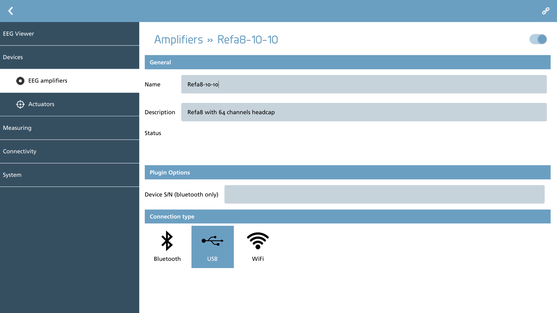
Setup of the legacy TMSi amplifiers is contingent upon the type of interface to which the device is connected.
For USB connections, it is essential to select "USB" as the connection type and to connect the amplifier to an available USB2 (or later) port. Once the indicator light on the Fiber-to-USB-Interface (FUSBI) illuminates, you may proceed with the additional configuration steps.
For Bluetooth and WiFi connections, ensure that the device is successfully connected to NeuroCenter® EEG through the preferred wireless interface. Notably, for Bluetooth connections, it is imperative to enter the serial number of the device, as this is necessary for the software to accurately recognize and identify the device.